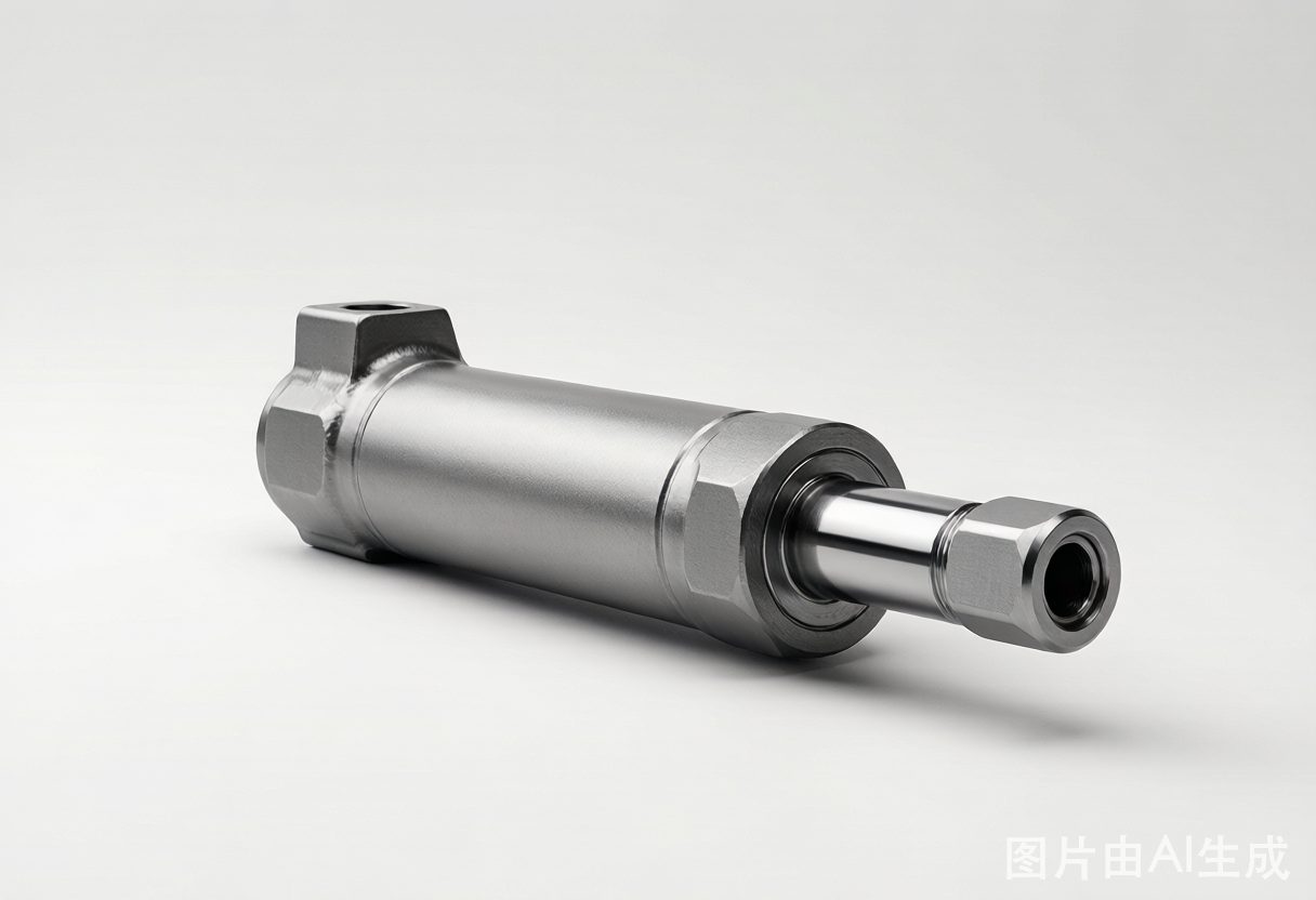
TL;DR: Size the bore from your load at system pressure, then pick a rod for the buckling and retract force you need, then set stroke from the implement's travel plus a little dead length. Three numbers — bore, rod, stroke — decide force, speed and mounting loads, and getting any one of them wrong costs you a re-order.
A farmer in Saxony called us last season about a front-loader cylinder that kept bending its rod. The machine ran a 160 bar system and the implement tipped at about 3.2 tonnes. The old rod was 40 mm on an 80 mm bore, and on every dump cycle it buckled just below the gland.
The fix wasn't a heavier pump or a stronger pin. It was a 50 mm rod with the same bore. Force barely changed; the buckling margin did.
Step 1: Bore from force
Bore sets your push force. The formula is simple: force equals pressure times area. Area is (π/4) times bore squared, so at a fixed pressure a 10% larger bore gives 21% more push.
Work backwards from the heaviest load your cylinder must lift, not the average one. A loader that normally carries 1.5 tonnes still has to clear the 2.8-tonne breakout spike on a full bucket, so size for the spike with 20–25% headroom.
| Bore (mm) | Push @ 160 bar (kN) | Push @ 210 bar (kN) | Typical implement |
|---|---|---|---|
| 50 | 31.4 | 41.2 | Light steering / top link |
| 63 | 49.9 | 65.5 | Mower lift, small planter |
| 80 | 80.4 | 105.6 | Loader boom, bale spike |
| 100 | 125.7 | 164.9 | Heavy loader, dump trailer |
| 125 | 196.3 | 257.7 | Deep ripper, forestry grapple |
Step 2: Rod for buckling and retract
Rod diameter is a two-sided decision. A fatter rod resists buckling on long, push-loaded strokes, but it also shrinks the annular area on the retract side. On a double-acting cylinder the pull force uses bore minus rod, so an oversized rod costs you retract force and slows retract speed for a given pump flow.
Rule of thumb from the shop floor: keep stroke-to-rod ratio under about 15:1 for a standard mount, and under 10:1 where the rod sees compression with side load. Our 50 mm rod on an 800 mm stroke was 16:1 — right at the edge, and the side load from the dump geometry pushed it over.
Step 3: Stroke and mounting
Stroke is the implement's full travel plus 20–40 mm of dead length so the piston never bottoms against the head. Measure travel with the implement at both ends, not from the catalogue, because pivot geometry multiplies a 200 mm lever swing into a 460 mm cylinder stroke on some loader arms.
Mounting style loads the numbers differently. Trunnion and clevis mounts put the load on the barrel and pins; foot and flange mounts put it into the end caps. A cylinder sized correctly for force can still fail if the mount can't take the moment, so confirm the mount before you finalize stroke.
Step 4: Flow, speed and pressure
Once bore and rod are set, check your pump can feed the speed you want. Extension speed in metres per second is flow divided by bore area, so a 63 mm bore at 40 L/min extends at about 0.21 m/s — fast enough for a mower lift, marginal for a loader.
Keep system pressure 20–25% under peak demand and make sure the cylinder's rated pressure clears your relief setting. If you are stuck between two bores, use our pressure converter to check force in bar, psi and MPa before you commit.
A worked example
A 2.5-tonne dump trailer lift needs about 24.5 kN at the ram. At 160 bar that points to a 63 mm bore, but the tilt geometry adds a 1.4× lever, so the real demand is closer to 34 kN. That pushes you to an 80 mm bore with a 45 mm rod on a 700 mm stroke — comfortably under the 15:1 ratio, with 18 months of warranty to back it.
If you are matching an existing machine rather than building new, send us the old cylinder's nameplate. We reverse the bore, rod and stroke from the part number and confirm a drop-in agricultural hydraulic cylinder or a custom build.
Specifying with HCIC
HCIC has sized and built agricultural cylinders since 1998, from 32 mm tie-rod units to 250 mm welded telescopics, across three plants and one R&D centre with 20+ engineers. We run 210,000 cylinders a year, 95% of them exported, to ISO 6020/6022/10100. Every cylinder ships with a test report, and a quote lands in your inbox within 48 hours.
Start from our cylinder range, check how the valve side fits with our load sensing vs flow sharing guide, or send a drawing through the contact page — MOQ is one piece, so a prototype and a fleet run are both welcome.
Frequently asked questions
What happens if I oversize a hydraulic cylinder?
You pay for steel and flow you don't use. The cylinder extends slower than the implement expects, the pump wastes energy at part load, and the extra weight raises cycle times on multi-function work.
Does rod diameter affect push or pull force?
Both. Push force uses the full bore area; pull force uses the annular area (bore minus rod). A large rod is stiffer against buckling but cuts retract force and increases the pump flow needed for a given retract speed.
How much safety factor should I leave on load?
Keep system pressure at least 20–25% below the peak load demand. For shock-heavy work such as loader impacts, aim higher, and confirm the cylinder's rated pressure clears the relief setting on the valve.
Can HCIC size a cylinder from an implement drawing?
Yes. Send the drawing or the old cylinder's nameplate, and our engineers confirm bore, rod, stroke and mountings against your circuit pressure. Quote within 48 hours, 18-month warranty, MOQ of one piece.